Resistance soldering is a technique similar to welding where a large electric current is passed through the joint of two metal objects. The electrical resistance of the joint itself causes localised heating — enough to cause normal electrical solder to melt and complete the joint. It can be a very effective way of soldering to heavy metal objects (such as rail) that conduct heat away from the joint too quickly to allow a convential soldering iron to work properly. It can also help minimise damage to nearby plastic rail ties!
Commercial resistance soldering stations are quite expensive — yet the principle behind the technique is very simple. Here are some ideas on how you can go about building your own resistance soldering iron.
The set-up is extremely simple. You need a “Scope” low voltage transformer capable of delivering ~30A across a short circuit without blowing up. “Scope” soldering irons date back to the glory days of valve radios and amplifiers, and they are not mainstream items any more. For an interesting history of their rise and fall, head over to the Australian Valve Amps web site.
You can still buy them new from a few places. I tried a quick search on Google for “scope soldering irons” and came up with quite a few hits: Wiltronics in Victoria look promising listing Scope transformers new for A$94 each. eBay is another good place to try to find a second hand one.
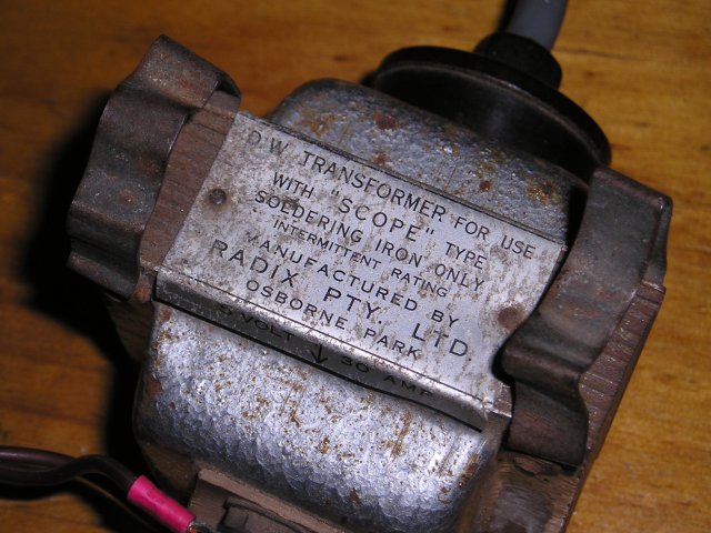
The transformer we are using was manufactured locally and is quite old. One of our members has had it for years. As you can see from the picture it is rated at 5V, 30A intermittent.
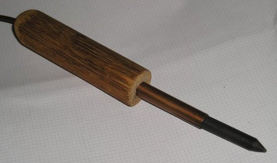
The tip is made from the end of broomstick, a short length of copper water pipe and the carbon core from a standard ‘D’ cell battery (carbon cell of course). Experience has shown that the cheaper the battery the better. Name brands (like Eveready or Duracell) tend to have quite porous, soft carbon rods. The really cheap ones (like you get as “own brand” in a supermarket or from salvage disposal stores) seem to use much harder carbon — which lasts longer in this application. Take care when cutting a dry cell battery open — it can be a messy job. Use some sandpaper to file a conical tip onto the carbon rod.
Drill a small hole through the middle of the broomstick to accept the wire and a larger hole half way through to accept the copper pipe as a press fit. Thread one wire through the broomstick and solder to the inside of the copper pipe. You want this joint to be very solid — spread it out over us much area of the copper that you can. Too small an area and it might get too hot itself during use and cause the solder to melt.Drill a small hole through the middle of the broomstick to accept the wire and a larger hole half way through to accept the copper pipe as a press fit. Thread one wire through the broomstick and solder to the inside of the copper pipe. You want this joint to be very solid — spread it out over us much area of the copper that you can. Too small an area and it might get too hot itself during use and cause the solder to melt.
You also need some two core flexible wire — pretty heavy gauge (it has to carry 30A after all!). I recommend some heavy duty speaker wire — basically the thicker the better.
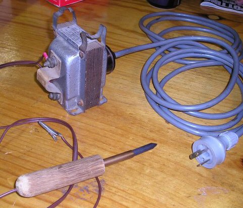
Cut a slit (with a Dremel or similar) into the other end of the copper pipe. This is so it can be expanded enough to accept the carbon rod — which itself is a simple press fit into the copper pipe. Press fit it all together. Put a large alligator clip on the end of the other wire. Attach the other ends of the two wires to the low voltage output of the transformer.
To use, attach the alligator clip to the rail. Hold the broomstick handle in one hand. Plug in the mains side of the transformer. Using the carbon tip, press the wire dropper you are soldering to the track on to the rail. Using your other hand simultaneously apply the solder — normal resin cored electronic solder is used. It gets hot very fast — there is 150W of heat concentrated right on the tip of the carbon rod as soon as you press it against the rail! Even though this is low voltage, you should wear safety glasses as there is a potential for sparks. It is possible to do it all by yourself but typically at the club it is done as a two person operation — one person holding the iron and the solder, the other person holding the dropper in position. This allows you to remove the iron to allow the solder to cool. Adding a foot switch on to the primary (mains) side of the transformer is a useful addition to allow one person operation.
As with convential soldering, cleanliness is paramount. If the joint is dirty, not only will the solder not stick to it, but it will probably not conduct much electricity and won’t get hot in the first place! I always recommend scraping the joint surfaces with a small file and/or “wet-and-dry” paper. Some club members like applying extra resin (or bees wax) prior to soldering, but I have never found it to be necessary myself.
Experiment and have fun!
For lots more information on resistance soldering techniques, try searching Google for “resistance soldering”.
Since passing this information on to other clubs, we received some useful feedback and suggestions. Instead of using a broom handle you can use an old soldering iron handle to hold the carbon rod. A size ‘C’ carbon cell battery has a small enough carbon rod for this purpose.
Hi, Im trying to get hold of (purchase) one pf the transformers you mention in your article. Its quite a difficult process. Can you recommend an alternative type of transformer. I have a variac transformer to vary voltage to the unit. Can you help? THANKS
Sorry Greg — I only have the links already in the article to offer. They all seem to still work even though this article is well over a decade old!
FWIW — we don’t use resistance soldering any more. Modern soldering irons are much better in terms of capability and performance. I find you can get far better results with a quality, modern soldering iron than you could with a home made resistance iron. 🙂
morning loking for a sooldering station used in the armed forces, has transformer ‑with a what looks like a pair of tweezers which when place and put to-gether on the item to be soldered it produces heat to the item and of course you can then solder the item?????????? they had them in the raaf base at richmond in NSW 40 years ago
Hi Tom — I suspect they would have been a form of resistance soldering iron for spot-weld style soldering. Tweezer style soldering irons do exist now mainly for SMD rework (e.g. https://www.weller-tools.com/professional/USA/us/Professional/Soldering+technology/Soldering+irons/Desoldering+tweezers/WTA+50+Set) but these are really just two fine tip soldering irons joined together in a spring loaded handle to make them convenient to use.
Maybe try doing some internet searches on ‘spot weld soldering’ is all I can suggest.
i have a scope soldering iron very old 5volts 30amp